© The Waters Trust, 2014, All Rights Reserved
Waters Turbine
Optimizing energy extraction from a moving fluid
Patent pending
The goal of a wind or water turbine
Convert the force of a fluid passing through a given area into electrical or mechanical force.
The Betz limit is discussed here.
Convert the force of a fluid passing through a given area into electrical or mechanical force.
The Betz limit is discussed here.
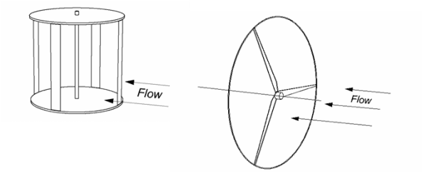
Current designs maximize aerodynamic efficiency like an aircraft. This results in long thin wings that comprise less than 5% of the total disk area in the region of maximum torque (the tip). Much of the air passes through unaffected or in a region that contributes low torque (the root). Only the tip of the blade maximizes leverage. A typical Horizontal axis (HAWT) and Vertical axis (VAWT) is shown below. A VAWT) has to fight upwind on one side as it rotates, usually resulting in lower efficiency than a HAWT.
Waters Turbine approach
1. Utilize the kinetic energy of as many molecules as possible.
3. Accelerate all flow prior to extraction of energy.
2. Divert all flow to the maximum point of leverage.
4. Place all of the blade area at both the maximum point of leverage and the highest flow velocity.
5. Use the same principle after extraction in reverse.
There are two choices for accelerating flow. Divert around an object or constrict through a narrower path. Diverting flow to the outside provides more leverage for a given size object and enables a simpler design. Generally, large costs more than small. Complex costs more than simple. Here is a basic design that meets the criteria.
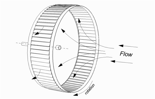
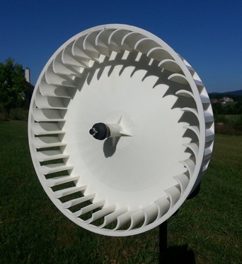
In the above illustration, all of the flow has to go around the back plate, accelerating in the process. A band of blades is mounted around the perimeter at both the maximum point of leverage and maximum flow velocity. As a result, all of the fluid is utilized and accelerated to maximum velocity prior to use.
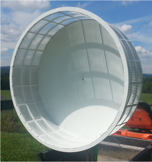
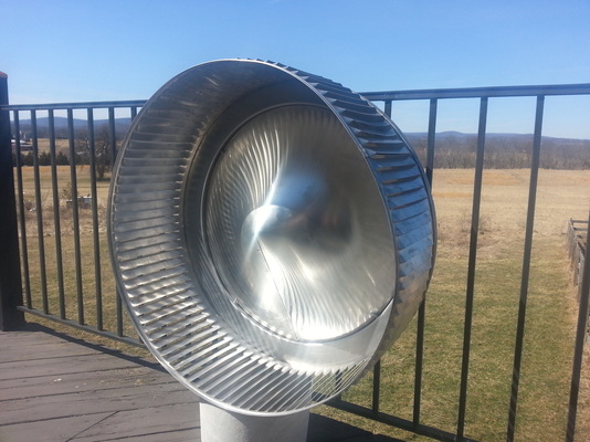
Waters Turbine
prototypes
prototypes
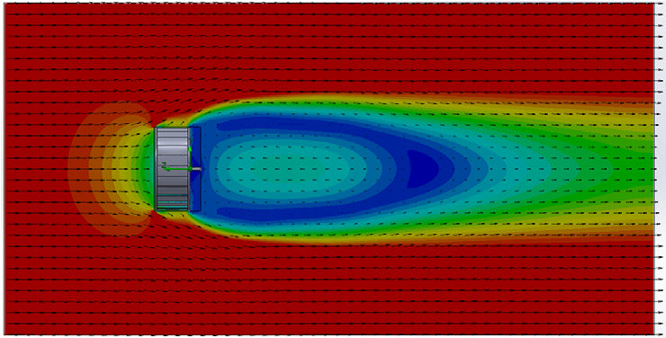
Velocity Profile
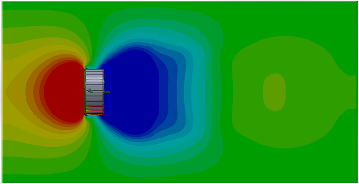
Pressure Profile
Thermal differential
I originally designed the Waters turbine to prove a point for a lecture I gave regarding Open System Physics and Thermodynamics. At the time I had little interest in wind turbines but had been involved in aviation and aerodynamics most of my life. The wind industry made an easy, somewhat devastating example.
A 4 month physicist study of the wind turbine confirmed the more complex explanation based on CFA (computer flow analysis) optimization.
Kinetic energy differential ( a fluid moving relative to a solid) can produce a thermal differential which can also be utilized to increase efficiency.
A recent discovery regarding bird evolution of black wings confirms this in basic terms. In this case a black wing increases the heat of the air passing over the upper surface, increasing efficiency by up to 20%.
Compressing air increases temperature. Lowering pressure reduces temperature. This is basically how an air conditioner works. The Waters turbine uses drag to create 3 different pressure zones in addition to ambient. As kinetic energy is extracted, temperature drops.
Even a small thermal differential represents a considerable amount of energy potential if designed correctly. With the 4 month physicist study, optimizing this showed a COP of up to 20 which means we were tapping a second thermal energy source. At first glance this appears to be a case of asymmetric thermodynamics but in reality the kinetic differential is just being exploited more efficiently.
Third party and direct comparison test
There have been three separate third party tests, including extensive computer flow analysis (CFA). My own direct comparative tests against a conventional high performance wind turbine in a broad range of conditions confirm theory. We ran extensive direct comparisons in real world conditions because 3rd party results seemed too high. An aerodynamicist study over several months of tests using CFA and wind tunnel tests showed up to 122 times more efficient than existing designs at 14 mph.
In my tests, the conventional design was a molded precision product with an accurate airfoil. Mine was far from optimized, using no airfoils (concrete vent) in order to establish the source of the efficiency gain that was in addition to aerodynamic gains.
Comparing my 4' design against a stock 5' three blade under the same load, the conventional product starts at over 7 mph and produces very little torque or rpm at that speed. My turbine, under the same load starts at under 1 mph. If the square force relationship is used that is 49 times more force required to turn the conventional design. If the cube rule is used the difference is 343 times. Then there is a size difference. The actual formula is more complex and varies with wind speed but the results are interesting. Startup velocity is just one factor but this shows that a much broader wind velocity range can be utilized.
Under extreme shaft load, the conventional turbine would not turn even at 28 mph. My design in the same conditions self starts at 11 mph.
These tests seem to confirm 3rd party results.
Test equipment involved a Prony brake (measuring torque), rpm meter and wind meter. Accuracy of both wind and rpm meters were within 3%. Prony brake measurements were comparative and direct, utilizing the same shafts, brakes, loads and conditions for both designs, operating at the same time in the same air.
